Which three authentication types can be used to authenticate users? (Choose three.)
A. Local database authentication
B. PingID
C. Kerberos single sign-on
D. GlobalProtect client
E. Cloud authentication service
Explanation:
Why These Options?
1.Local Database Authentication (A):
The firewall stores usernames/passwords locally (Device > Administrators).
Used for admin login or captive portal authentication.
2.Kerberos Single Sign-On (C):
Integrates with Active Directory for seamless authentication (e.g., for User-ID or captive portal).
Users are automatically authenticated via their domain credentials.
3.Cloud Authentication Service (E):
Supports SAML, OAUTH, or LDAP via cloud providers (e.g., Azure AD, Okta).
Used for GlobalProtect, admin login, or captive portal.
Why Not Others?
B. PingID
This is a specific MFA product, not a general authentication type (it would fall under cloud authentication).
D. GlobalProtect Client
This is a VPN client, not an authentication method (it uses other methods like SAML or local DB).
Reference:
Palo Alto Authentication Guide:
"Local, Kerberos, and cloud authentication are core methods for user verification."
What type of NAT is required to configure transparent proxy?
A. Source translation with Dynamic IP and Port
B. Destination translation with Static IP
C. Source translation with Static IP
D. Destination translation with Dynamic IP
Explanation:
To configure transparent proxy on a Palo Alto Networks firewall, the required NAT type is:
Destination translation with Dynamic IP
This NAT configuration allows the firewall to:
Intercept outbound traffic transparently
Redirect it to the proxy engine (typically hosted on a loopback interface)
Rewrite the destination IP dynamically while preserving session integrity
This setup is essential for inline transparent proxy deployments, where the client is unaware of the proxy and no explicit configuration (like PAC files) is used.
Authoritative Source:
Palo Alto Networks – Configure Transparent Proxy
Ace4Sure – Transparent Proxy NAT Type
A firewall engineer creates a NAT rule to translate IP address 1.1.1.10 to 192.168.1.10. The engineer also plans to enable DNS rewrite so that the firewall rewrites the IPv4 address in a DNS response based on the original destination IP address and translated destination IP address configured for the rule. The engineer wants the firewall to rewrite a DNS response of 1.1.1.10 to 192.168.1.10. What should the engineer do to complete the configuration?
A. Create a U-Turn NAT to translate the destination IP address 192.168.1.10 to 1.1.1.10 with the destination port equal to UDP/53.
B. Enable DNS rewrite under the destination address translation in the Translated Packet section of the NAT rule with the direction Forward.
C. Enable DNS rewrite under the destination address translation in the Translated Packet section of the NAT rule with the direction Reverse.
D. Create a U-Turn NAT to translate the destination IP address 1.1.1.10 to 192.168.1.10 with the destination port equal to UDP/53.
Explanation:
The engineer wants the firewall to rewrite a DNS response of 1.1.1.10 to 192.168.1.10, which means the IP address in the DNS response matches the original destination address in the NAT rule. Therefore, the correct DNS rewrite direction is:
Forward — translates the IP in the DNS response using the same translation as the NAT rule.
To implement this:
Go to Policies > NAT and edit the NAT rule.
In the Translated Packet section:
Set Translation Type to Static IP
Enter the Translated Address (192.168.1.10)
Enable DNS Rewrite
Set Direction to Forward
Commit the changes.
📘 Palo Alto Networks – Configure Destination NAT with DNS Rewrite
Exhibit.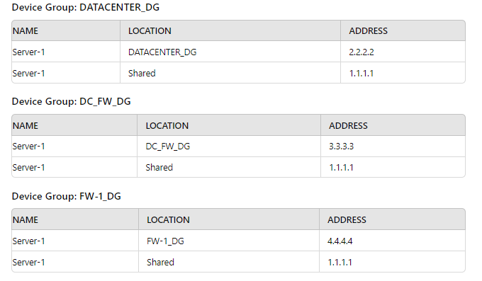
Review the screenshots and consider the following information:
1. FW-1is assigned to the FW-1_DG device group, and FW-2 is assigned to
OFFICE_FW_DC
2. There are no objects configured in REGIONAL_DG and OFFICE_FW_DG device groups.
Which IP address will be pushed to the firewalls inside Address Object Server-1?
A. Server-1 on FW-1 will have IP 4.4.4.4. Server-1 on FW-2 will have IP 1.1.1.1
B. Server-1 on FW-1 will have IR 111.1. Server-1 will not be pushed to FW-2.
C. Server-1 on FW-1 will have IP 2.2.2.2. Server-1 will not be pushed to FW-2.
D. Server-1 on FW-1 will have IP 3.3.3.3. Server-1 will not be pushed to FW-2.
Explanation:
Palo Alto Networks Panorama uses a hierarchical device group structure where object definitions (like address objects) can be overridden at lower levels. Here's how it applies:
FW-1 is in FW-1_DG:
Server-1 is defined in FW-1_DG with IP 4.4.4.4
This overrides any shared or higher-level definitions.
So FW-1 receives Server-1 = 4.4.4.4
FW-2 is in OFFICE_FW_DC:
No Server-1 object is defined in OFFICE_FW_DC, OFFICE_FW_DG, or REGIONAL_DG.
The only available definition is in the Shared context: 1.1.1.1
So FW-2 receives Server-1 = 1.1.1.1
📚 Reference:
Palo Alto Networks Panorama Admin Guide – Device Group and Object Hierarchy
Object override behavior: Lower-level device group definitions take precedence over Shared or parent group definitions.
To ensure that a Security policy has the highest priority, how should an administrator configure a Security policy in the device group hierarchy?
A. Add the policy to the target device group and apply a master device to the device group.
B. Reference the targeted device's templates in the target device group.
C. Clone the security policy and add it to the other device groups.
D. Add the policy in the shared device group as a pre-rule
Explanation:
In Palo Alto Networks Panorama device group hierarchy, security policy precedence is determined by two things:
1.Rule location (pre-rule vs post-rule vs local rules):
Pre-rules (defined in Panorama) are evaluated before any local device rules.
Post-rules (defined in Panorama) are evaluated after all local device rules.
Local rules (on the firewall itself or pushed to the device group) sit in between pre- and post-rules.
🔑 So, Pre-rules always have the highest priority.
2.Device group hierarchy (shared vs child device group):
Policies created in the Shared device group are inherited by all child device groups.
Placing the policy in the Shared device group as a pre-rule ensures it applies everywhere, and always comes first.
Why the other options are incorrect:
A. Add the policy to the target device group and apply a master device to the device group.
❌ Wrong. Adding it to a device group doesn’t guarantee highest priority. It will still be evaluated in the middle (local rules). The “master device” concept is for template settings, not for controlling policy priority.
B. Reference the targeted device's templates in the target device group.
❌ Wrong. Templates control network and device configuration (interfaces, zones, routing, etc.), not security rule priority.
C. Clone the security policy and add it to the other device groups.
❌ Wrong. Cloning distributes the policy, but it still won’t guarantee the highest priority unless it’s placed as a pre-rule. It also makes management harder (duplicate configs).
D. Add the policy in the shared device group as a pre-rule.
✅ Correct. This guarantees it applies to all firewalls first, before local rules. This is the best practice when a global policy must take precedence.
Reference:
Palo Alto Networks TechDocs: Policy Rulebase Precedence
Palo Alto Networks: Shared, Pre, and Post Rules in Panorama
A standalone firewall with local objects and policies needs to be migrated into Panorama. What procedure should you use so Panorama is fully managing the firewall?
A. Use the "import device configuration to Panorama" operation, commit to Panorama, then "export or push device config bundle" to push the configuration.
B. Use the "import Panorama configuration snapshot" operation, commit to Panorama, then "export or push device config bundle" to push the configuration.
C. Use the "import device configuration to Panorama" operation, commit to Panorama, then perform a device-group commit push with "include device and network templates".
D. Use the "import Panorama configuration snapshot" operation, commit to Panorama, then perform a device-group commit push with "include device and network templates".
Explanation:
To migrate a standalone firewall into Panorama management, the correct procedure involves importing its configuration and converting it into Panorama-managed objects (device groups and templates). Here's the step-by-step logic:
1: Import Device Configuration to Panorama
Use “Import device configuration to Panorama” to bring in the firewall’s local configuration.
This creates:
A device group for policies and objects.
A template for network and system settings.
📚 Reference:
Palo Alto Networks – Panorama Admin Guide: Import a Firewall Configuration
2: Commit to Panorama
This saves the imported configuration into Panorama’s database.
No changes are pushed to the firewall yet.
3: Push Configuration to Firewall
Use “Commit to Device Group” and select “Include device and network templates”.
This pushes both:
Device group policies/objects
Template settings (interfaces, zones, etc.)
This step ensures the firewall is now fully managed by Panorama.
❌ Why Other Options Are Wrong:
A. Incorrect because “export or push device config bundle” is used for bootstrapping or initial provisioning — not for migrating an existing standalone firewall.
B & D. Incorrect because “import Panorama configuration snapshot” is used to restore Panorama’s own config — not to import a firewall’s config.
An administrator is informed that the engineer who previously managed all the VPNs has left the company. According to company policies the administrator must update all the IPSec VPNs with new pre-shared keys Where are the pre-shared keys located on the firewall?
A. Network/lPSec Tunnels
B. Network/Network Profiles/IKE Gateways
C. Network/Network ProfilesTlPSec Crypto
D. Network/Network Profiles/IKE Crypto
Explanation :
In a Palo Alto Networks firewall, pre-shared keys for IPSec VPNs are configured in the IKE Gateway settings, located under Network > Network Profiles > IKE Gateways. The pre-shared key is used during the Internet Key Exchange (IKE) Phase 1 to authenticate VPN peers. The IKE Gateway profile defines parameters like the authentication method, peer IP, and pre-shared key. To update the key, an administrator navigates to the IKE Gateway configuration, selects the profile, and modifies the Pre-Shared Key field under the General tab’s Authentication section. After updating, the change must be committed, and the new key coordinated with the peer device to maintain connectivity.
This is critical for the PCNSE exam, as it tests understanding of VPN configuration. The Palo Alto Networks PAN-OS 11.1 Administrator’s Guide confirms that pre-shared keys are set in the IKE Gateway, emphasizing their role in IKE Phase 1 authentication.
Why Other Options Are Incorrect:
A. Network/IPSec Tunnels:
This section configures IPSec Phase 2 settings, such as tunnel interfaces and encryption for data traffic. It references the IKE Gateway for Phase 1 but does not store the pre-shared key. Per the PCNSE Study Guide, IPSec Tunnels rely on IKE Gateways for authentication settings.
C. Network/Network Profiles/IPSec Crypto:
IPSec Crypto profiles define Phase 2 cryptographic settings (e.g., encryption and authentication algorithms) but do not include pre-shared keys, which are specific to Phase 1. The PAN-OS 11.1 Administrator’s Guide clarifies that IPSec Crypto is for data tunnel security, not peer authentication.
D. Network/Network Profiles/IKE Crypto:
IKE Crypto profiles specify cryptographic algorithms for IKE Phase 1 (e.g., encryption, Diffie-Hellman group) but do not contain the pre-shared key. The key is set in the IKE Gateway, as noted in the PCNSE Study Guide.
Practical Steps:
Go to Network > Network Profiles > IKE Gateways.
Select the IKE Gateway profile for the VPN.
In the General tab, under Authentication, update the Pre-Shared Key.
Commit the configuration and coordinate with the peer.
References:
Palo Alto Networks PAN-OS 11.1 Administrator’s Guide: Details IKE Gateway configuration for pre-shared keys.
Palo Alto Networks PCNSE Study Guide: Explains VPN configuration, emphasizing IKE Gateway for authentication.
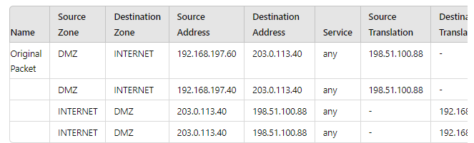
A new application server 192.168.197.40 has been deployed in the DMZ. There are no public IP addresses available resulting in the server sharing MAT IP 198 51 100 B8 with another OMZ serve that uses IP address 192 168 19? 60 Firewall security and NAT rules have been configured The application team has confirmed mat the new server is able to establish a secure connection to an external database with IP address 203.0.113.40. The database team reports that they are unable to establish a secure connection to 196 51 100 88 from 203.0.113.40 However it confirm a successful prig test to 198 51 100 88 Referring to the MAT configuration and traffic logs provided how can the firewall engineer resolve the situation and ensure inbound and outbound connections work concurrently for both DMZ servers?
A. Replace the two NAT rules with a single rule that has both DMZ servers as "Source Address." both external servers as "Destination Address." and Source Translation remaining as is with bidirectional option enabled
B. Sharing a single NAT IP is possible for outbound connectivity not for inbound, therefore, a new public IP address must be obtained for the new DMZ server and used in the NAT rule 6 DMZ server 2.
C. Configure separate source NAT and destination NAT rules for the two DMZ servers without using the bidirectional option.
D. Move the NAT rule 6 DMZ server 2 above NAT rule 5 DMZ server 1.
Explanation:
Let's analyze the provided information and the core problem.
The Scenario:
Two servers in the DMZ: 192.168.197.60 (Server 1) and 192.168.197.40 (Server 2).
One public IP (198.51.100.88) is shared for both servers.
Outbound works: Both servers can initiate connections to the external database (203.0.113.40). This is handled by the first two NAT rules (Source NAT).
Inbound fails: The external database (203.0.113.40) cannot initiate a connection back to 198.51.100.88. This is the problem.
Why Inbound Fails: The "Hairpin" NAT Problem
The provided NAT rules are bidirectional (implied by the structure, a single rule handling both directions). For inbound traffic, the firewall sees a packet destined for its public IP (198.51.100.88). It needs to know which internal server (192.168.197.60 or 192.168.197.40) to send it to.
A single bidirectional NAT rule using a shared IP cannot make this decision. There is no information in the inbound packet (from 203.0.113.40 to 198.51.100.88) that tells the firewall which internal host is the intended recipient. This is a classic limitation of overloading a single IP for multiple hosts without a differentiating factor like destination port (which is any in this case).
The Solution: Decoupling NAT
The solution is to break the single, ambiguous bidirectional rule into two separate, explicit rules:
Source NAT Rules (Outbound): Keep the two existing outbound rules. These handle traffic originating from the DMZ servers. The firewall can easily identify the correct source IP to translate to based on the originating internal IP.
Destination NAT Rules (Inbound): Create two new, separate Destination NAT (DNAT) rules. These rules are placed in a different rulebase and are evaluated based on the destination of the incoming packet.
Rule A: If destination IP is 198.51.100.88 and destination port is [Port used by Server 1], then translate destination to 192.168.197.60.
Rule B: If destination IP is 198.51.100.88 and destination port is [Port used by Server 2], then translate destination to 192.168.197.40.
By using the destination port (which the application team must define), the firewall now has the critical information needed to disambiguate the inbound traffic and send it to the correct server. The "bidirectional" option is not used; outbound is handled by Source NAT rules, and inbound is handled by completely separate Destination NAT rules.
Detailed Analysis of the Other Options:
A. Replace the two NAT rules with a single rule... with bidirectional option enabled.
Why it's wrong: This makes the problem worse, not better. Combining the rules into one giant rule still suffers from the same fundamental flaw: the firewall cannot determine the correct destination for an inbound connection. The bidirectional option depends on a unique public:private IP mapping, which is impossible here as the mapping is 1:2.
B. Sharing a single NAT IP is possible for outbound connectivity not for inbound...
Why it's wrong: While this statement is partially true for this specific case (with any service), it is not the correct answer. It is absolutely possible to share a single IP for inbound connectivity using port-based Destination NAT (as described in solution C). This is how web hosting companies run multiple HTTPS sites (port 443) on a single IP—they can't, they use SNI, but the NAT concept is similar for other protocols. The answer suggests giving up instead of implementing the correct technical solution.
D. Move the NAT rule 6 DMZ server 2 above NAT rule 5 DMZ server 1.
Why it's wrong: The order of NAT rules is crucial, but it has no effect on this problem. The issue is not the evaluation order of the outbound rules; it's the fundamental inability of the inbound evaluation to choose between two internal hosts. Reordering two identically flawed rules does not fix the flaw.
PCNSE Exam Reference & Key Takeaway:
Core Concept: Understand the difference and use cases for Source NAT vs. Destination NAT. Bidirectional NAT is simple but requires a 1:1 IP mapping.
NAT Order of Operations:Know that Destination NAT rules are processed before Security policies, and Source NAT rules are processed after Security policies (on egress). This question hinges on the need for a specific Destination NAT rule.
Troubleshooting: Use tools like show session all and the traffic logs to see the pre- and post-NAT IP addresses, which would clearly show the inbound packet being dropped because no DNAT rule exists to translate 198.51.100.88 to a specific private IP.
Real-World Application: This is a very common scenario. The correct design is to use separate DNAT rules that include destination port to uniquely identify the service on each server behind the shared IP.
| Page 10 out of 41 Pages |
| Palo Alto PCNSE Practice Test Home | Previous |
Contact Us - Privacy Policy ... Copyright © - All Rights Reserved